UV LED Exposure Box - Test Bench
To make your PCBs you will need an UV exposure box. It is very easy to build an UV exposure box, but classically you will make it with some UV tubes. You have an alternative which consists using UV LEDs.
UV LED exposure boxes can be found on the Internet, but there is not always PCB examples or comments. It's why I built a small UV LED exposure box to know if it is a good solution and if it really works well. You will find here the realization and the results I got.
1. The LEDs
The choice of the UV LEDs is important. LEDs have many characteristics, and every UV LEDs will not agree with our need. Those characteristics are: the wave length, the luminous intensity, the viewing angle...
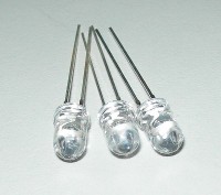
I have choosen those UV LEDs:
- size: 5mm
- wave length: 390/395nm
- forward voltage: 3.2/3.8 Volts
- intensity: 2000mcd
- viewing angle: 20/25 degree
- continuous forward current: 30mA.
100 LEDs cost about $10 or less on eBay so it is not so expensive.
2. Schematic and realization of the UV LEDs panel
I decided to connect the LEDs like you can see on the schematic below.
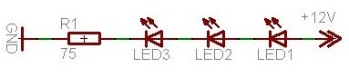
The three LEDs are powered with a 12.3 volts supply. I have used a linear regulator (LM317), but I think it is possible to use a switching regulator, saving energy.
I have connected 32 groups of 3 LEDs, making an exposure box with 96 UV LEDs. Dimensions of the exposure box are 100x150mm.
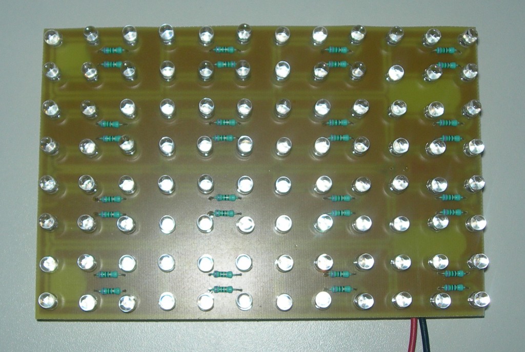
The panel comsumption is about 1A @ 12.3 volts.
Conclusions
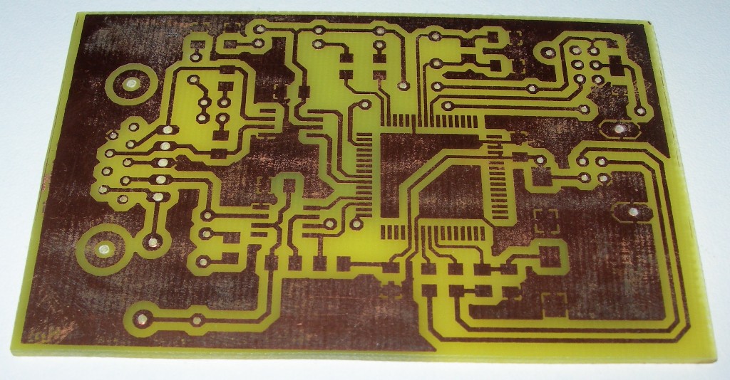
With this UV LED exposure box, I made the PCB you can see below.
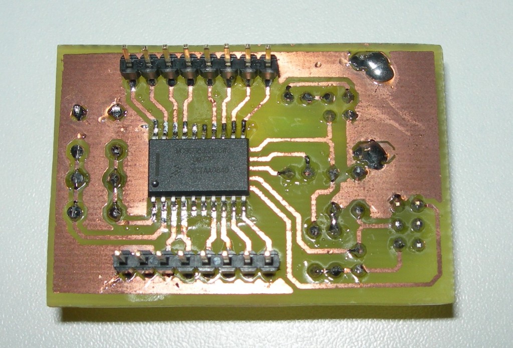
You will maybe recognize my S08JS16 evaluation board used in the USB with S08JS16 device tutorial. I put the PCB only 2"30' in the exposure box to get this result.
I also made a satisfaying PCB with a QFP64 integrated circuit as shown below (the color of the copper is maybe a little strange, but I think it is because I put the PCB too long time in the expose box, and maybe because the PCB was old. I recommend to not make too much stock of PCB to be sure of the quality of the results).